1. Open Test project
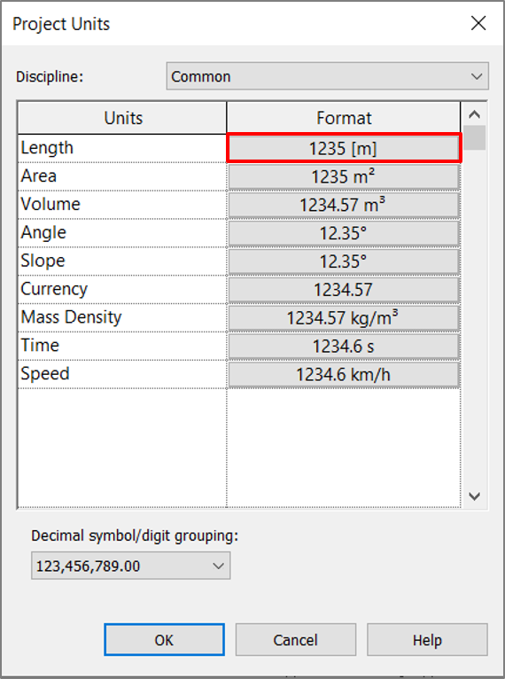
Download test Revit project (“Villa Savoye RVTXX.rvt”) and open it. Check that project units are set to meters. Then launch Dynamo.
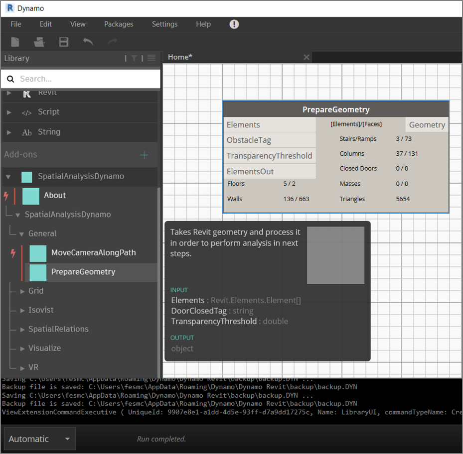
2. Add “Prepare Geometry” Component
Add the “PrepareGeometry” component from the “General” tab to the canvas. This component is a start point for almost all workflows in this package. It processes all necessary Revit geometry in order to perform analysis in next steps with other components.
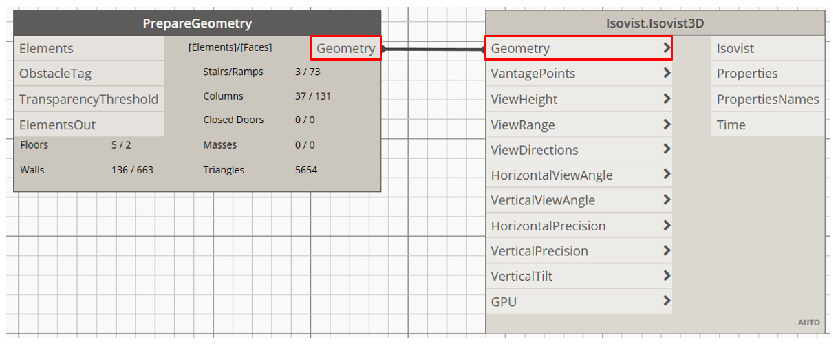
3. Add “Isovist 3D” Component
Add the “Isovist3D” component from the “Isovist” tab. Connect the “Geometry” output of the “PrepareGeometry” component with corresponding input. The “Isovist3D” component is similar to the “Isovist2D” component discussed in the previous tutorial, so it’s inputs will be discussed not in detail as they are almost the same but with adding a 3d dimension.
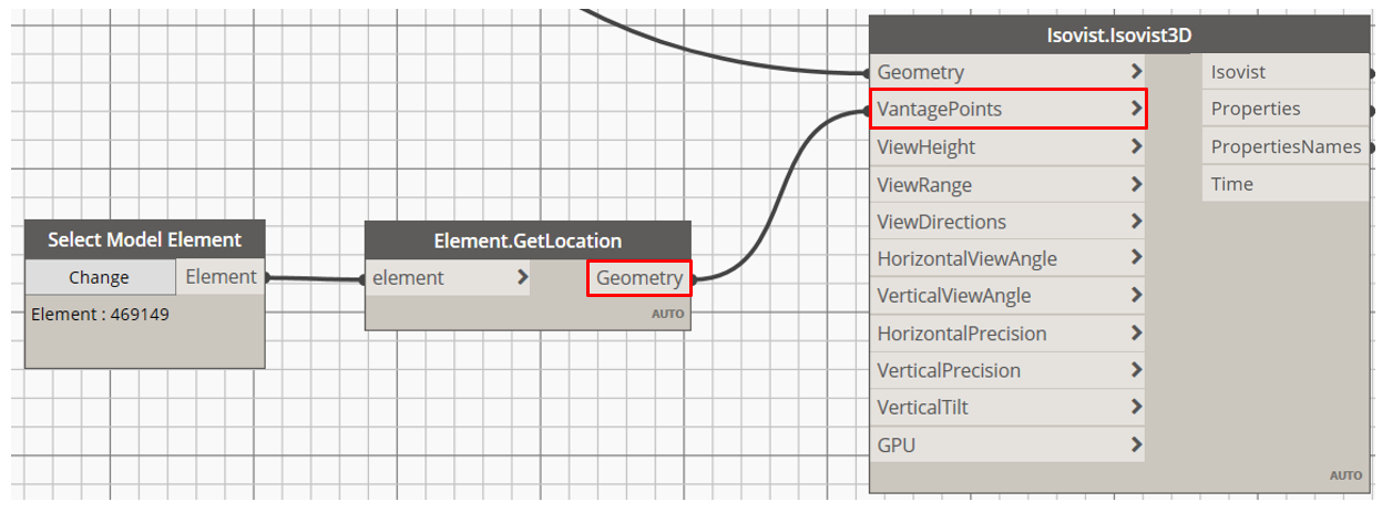
4. Select vantage point
Add the “Select Model Element” component to the canvas. Click “Select” button and select human object. Add “GetLocation” component to get the location point and provide it as “VantagePoint” input. After this isovist will be calculated.
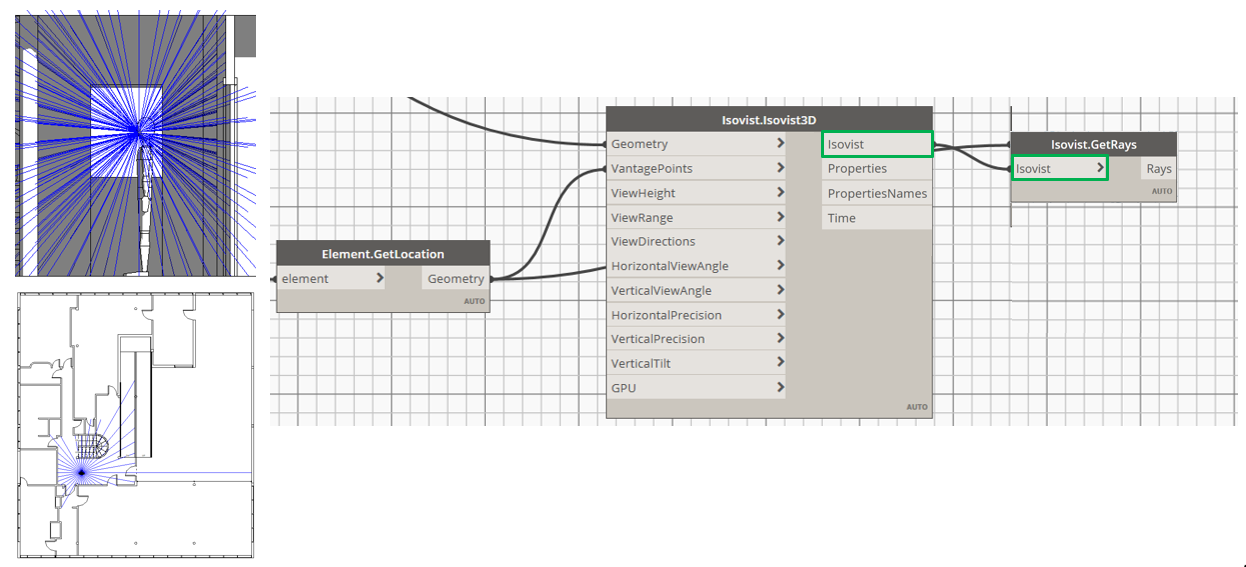
5. Display isovist rays
To display rays geometry add the “GetRays” component from the “Isovist” tab. Connect the “Isovist” output of the “Isovist3D” component with the “Isovist” input. After this - rays will appear in active Revit view.
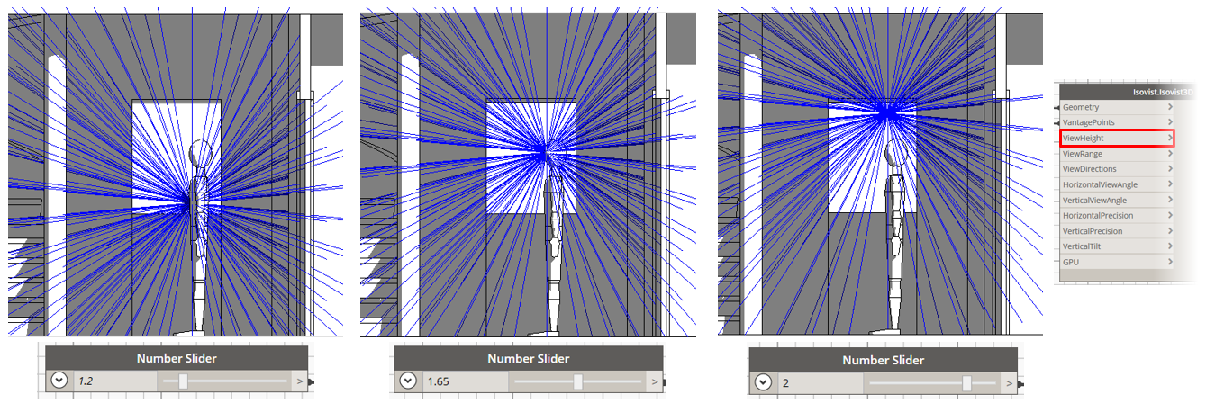
6. Isovist settings: View Height
You can manipulate geometry of isovist by input parameters. First, the “ViewHeight” input controls a height of the viewer. By default it is set to 1.6m. In the “Isovist 2D” component viewer height was controlled by the value at which section was made. Here, in order to correctly display rays after changing the “ViewHeight” input, the corresponding input should be changed in the “GetRays” component as well.
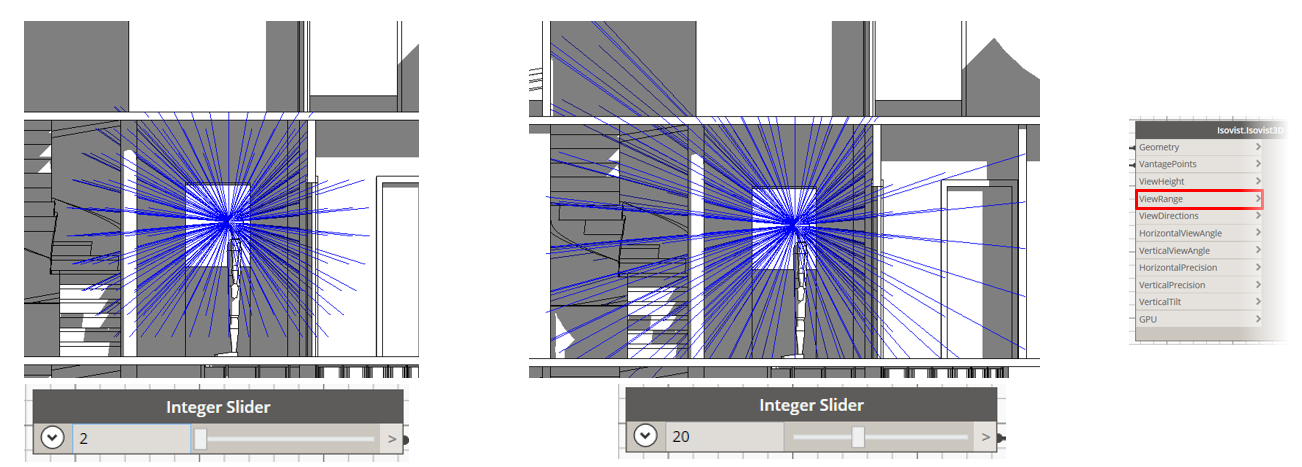
7. Isovist settings: View Range
The “ViewRange” input controls a length of rays outcoming from a viewer position (i.e. vantage point) and defines how far one can see. Default value is set to 20m.
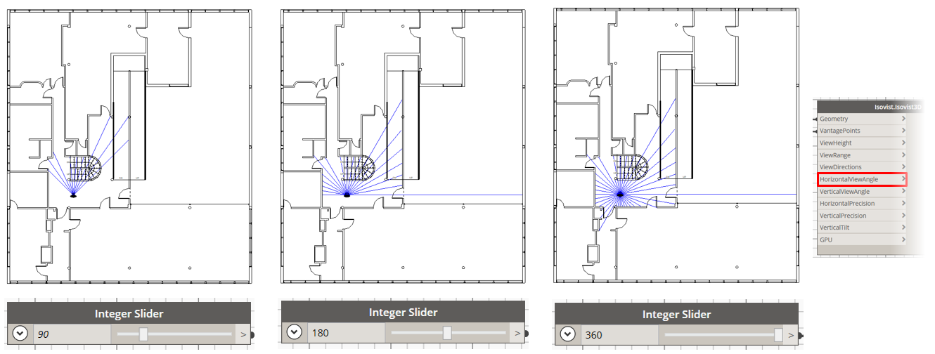
8. Isovist settings: Horizontal View Angle
The “HorizontalViewAngle” input controls horizontal viewing angle (same as in the “Isovist 2D” component) and defines the field of view. Default value is set to 360°.
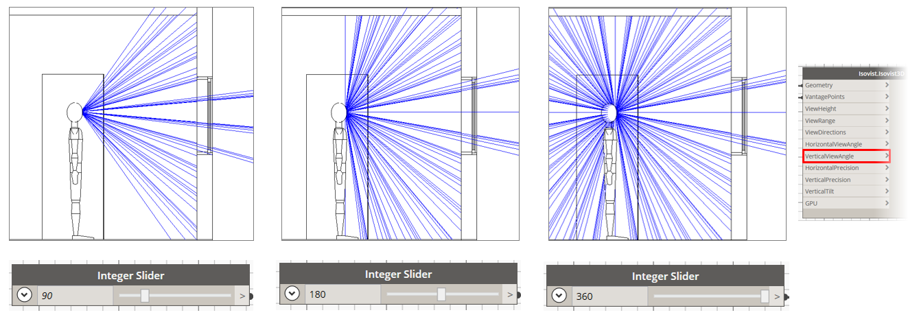
9. Isovist settings: Vertical View Angle
The “VerticalViewAngle” input controls vertical viewing angle and defines the field of view. Default value is set to 90°.
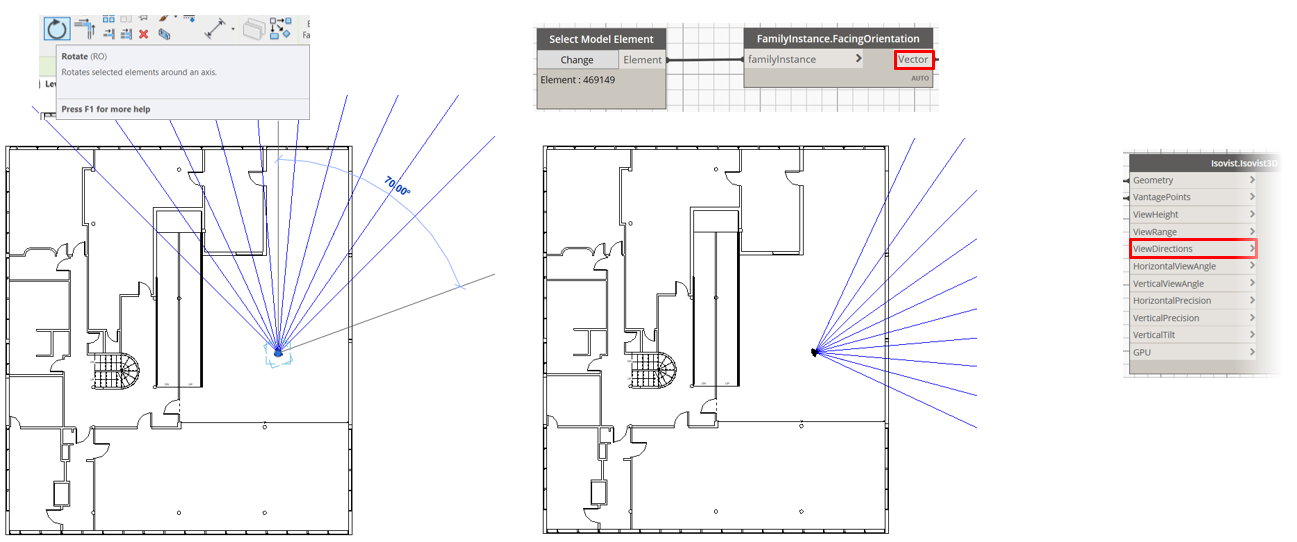
10. Isovist settings: View directions
The “ViewDirections” input controls direction vector for a vantage point and defines in which direction (e.g. left or right) the viewer looks. It is not taken into account, if the “HorizontalViewAngle” input is set to 360°. As was discussed in tutorial to the “Isovist 2D” component it is possible to link the rotation of the human object with isovist direction vector, for this purposes use the “FacingOrientation” component.
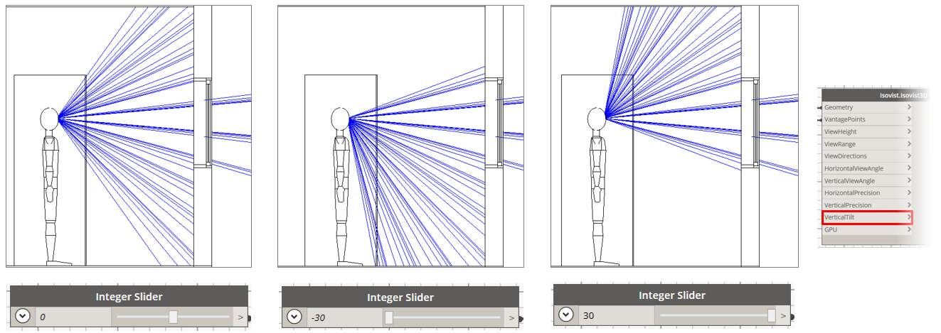
11. Isovist settings: Vertical Tilt
The “VerticalTilt” input controls direction vector for a vantage point in a vertical manner and defines in which direction (e.g. up or down) the viewer looks. By default tilt is set to the 0°.
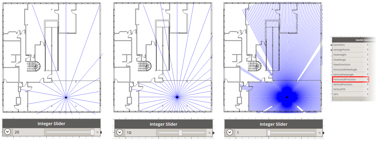
12. Isovist settings: Horizontal Precision
The “HorizontalPrecision” input controls a step angle between horizontally generated rays. By default it is set to 10° between rays. The denser rays generation is the more precise isovist geometry is built, but the more time could be required for calculations.
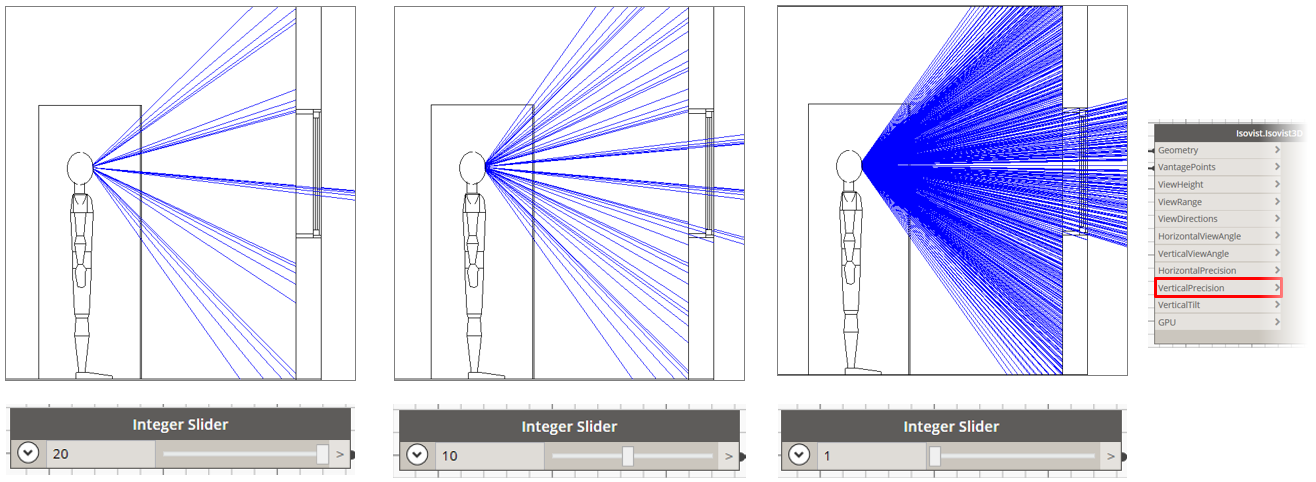
13. Isovist settings: Vertical Precision
The “VerticalPrecision” input controls a step angle between vertically generated rays. By default it is set to 10° between rays. The denser rays generation is the more precise isovist geometry is built, but the more time could be required for calculations.
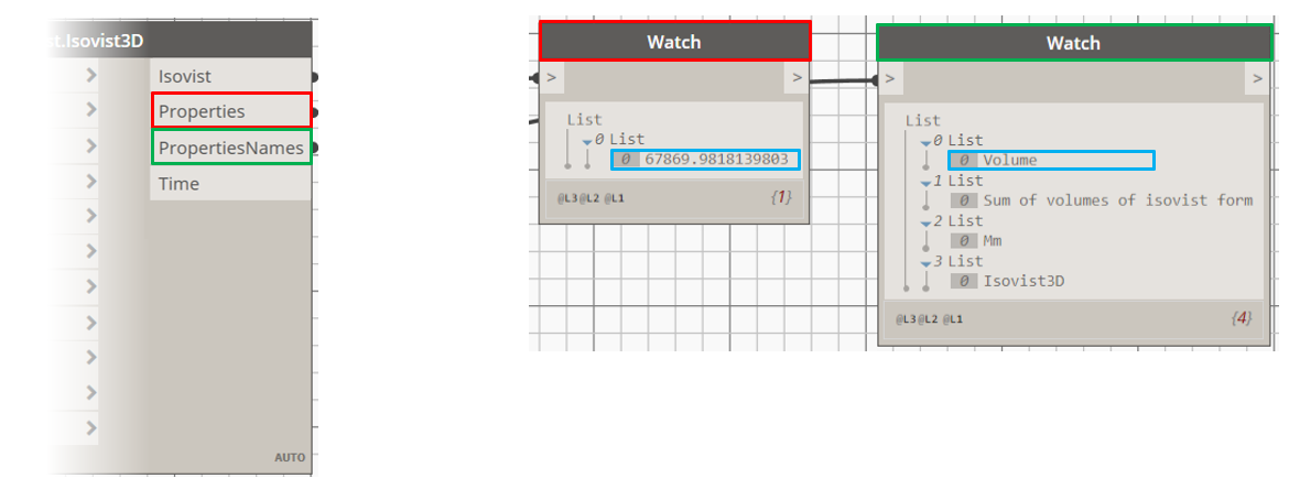
14. Isovist Properties
The “Isovist3D” component calculates not only the rays geometry but also isovist properties per each vantage point. It returns the list of properties values (for 3D Isovist now only “Volume” is calculated) as “Properties” output and their titles (0 List), description (1 List) and units (2 List) as the “PropertiesNames” output in the same order. Add the “Watch” component and connect it with the “Properties” output to see the values. Do the same action for the “PropertiesNames” output. Matching two lists we can say, for example, that the “Volume” is equal to 67869.98 mm3.
SUM UP