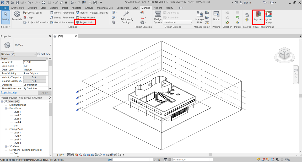
1. Open Test project
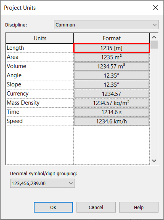
Download test Revit project (“Villa Savoye RVTXX.rvt”) and open it. Check that project units are set to meters. Then launch Dynamo.
2. Add “PREPARE GEOMETRY” Component
Add the “PrepareGeometry” component from the “General” tab to the canvas. This component is a start point for almost all workflows in this package. It processes all necessary Revit geometry in order to perform analysis in next steps with other components.
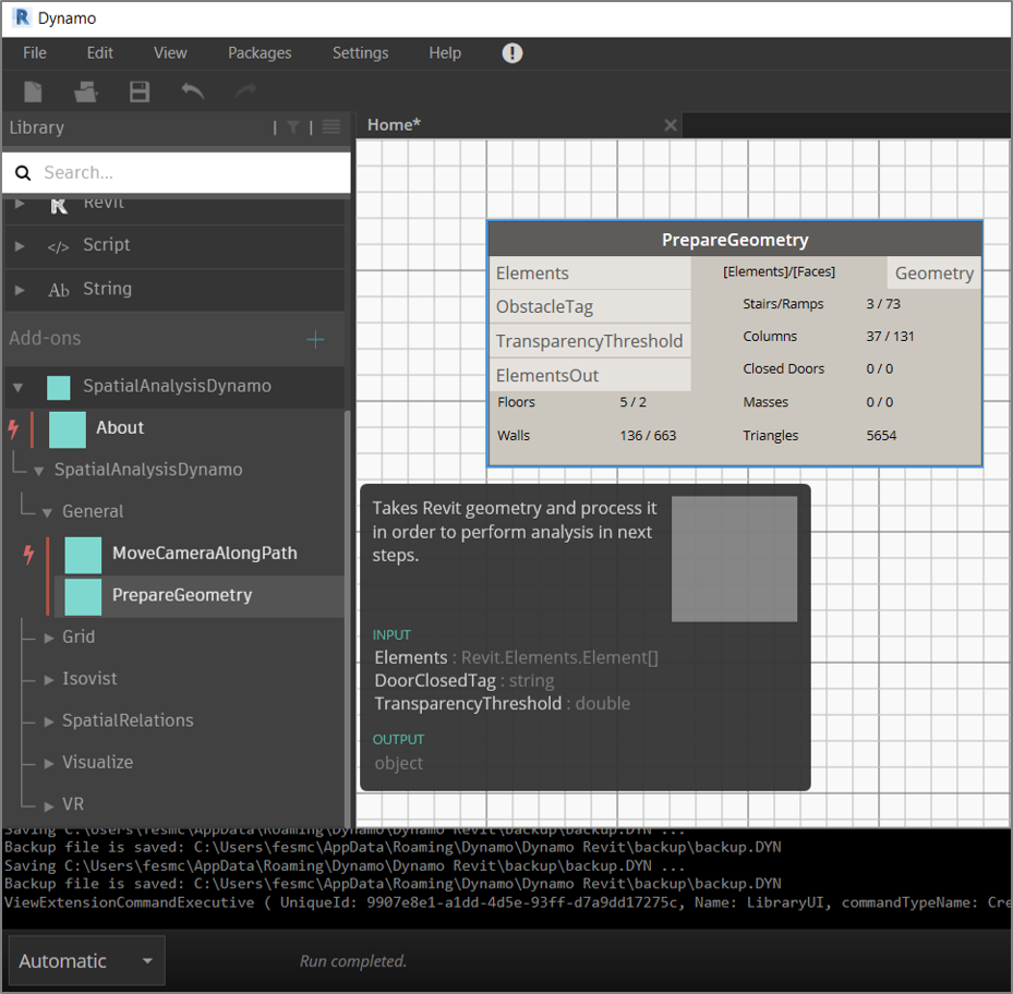
Component displays 5 main types with which the package works:
The last title here is “Triangles”, which shows the number of triangles in the all processed geometry (not for the whole scene but only for geometry which mentioned above). The higher this number is, the longer the computation time for the analysis components can be expected.
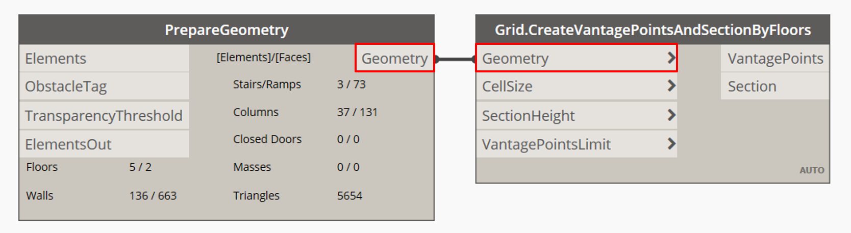
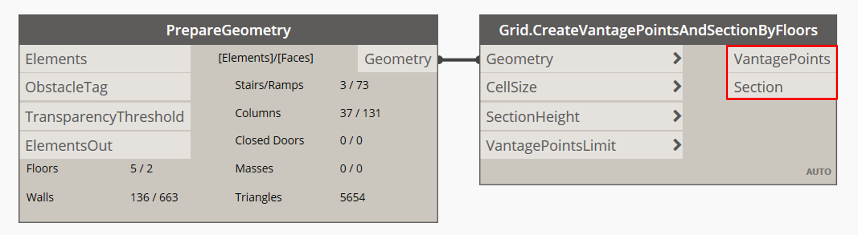
3. Add “Create Vantage Points And Section By Floors” component
Add the “CreateVantagePointsAndSectionByFloors” component from the “Grid” tab to the canvas. This component is also frequently used during various workflows. Connect the “Geometry” output from the “PrepareGeometry” component with the “Geometry” input of the “CreateVantagePointsAndSectionByFloors” component.
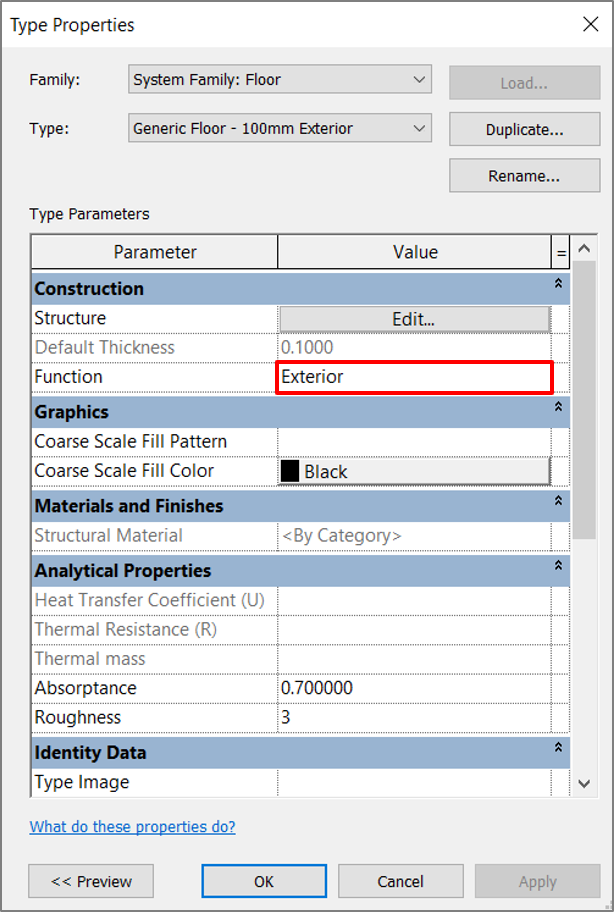
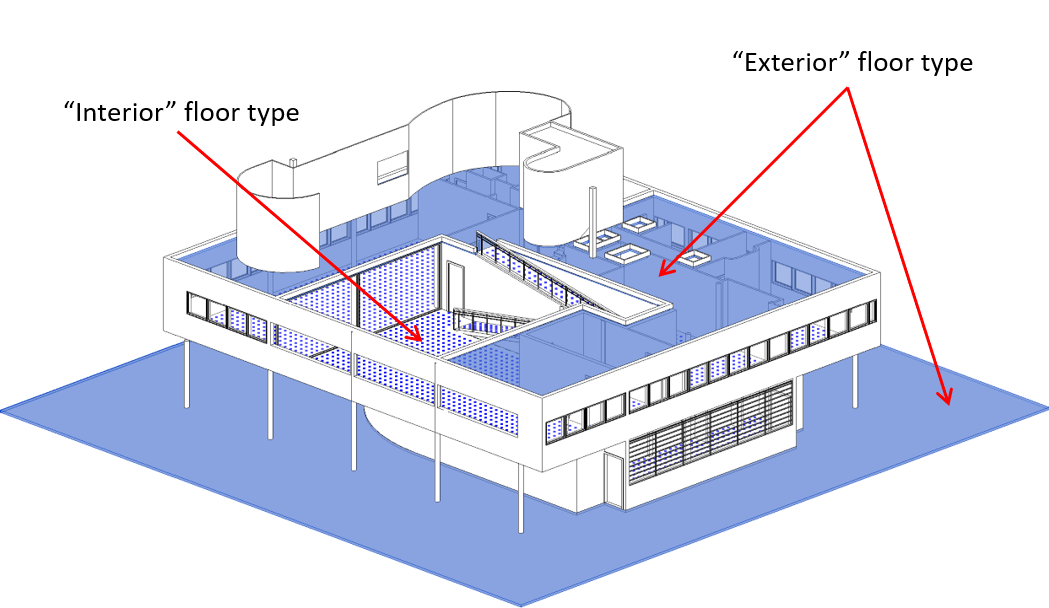
4. Including/excluding floors from calculation
Now a grid of vantage points for every floor object marked as “interior” and for all stairs/rumps will be created. In example below the roof floor and the ground floor are both of type which is marked as “exterior” and, therefore, it is not used for grid generation.
5. “Create Vantage Points And Section By Floors” component: outputs
The “CreateVantagePointsAndSectionByFloors” component has two outputs the “VantagePoints” and the “Section”. The “VantagePoints” represents the grid which discretizes the analysis surfaces. The “Section” output is needed for other components to perform 2D analysis.
6. Increase\decrease grid size
To increase/decrease frequency of the vantage points a “CellSize” input parameter could be manipulated. Default step between the points in the grid is 0.3m.
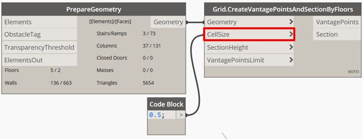
The denser the grid, the more accurate the following analysis results will be, but at the same time the more computation power it needs. On the other side, a sparse grid can create a situation when a step between points is larger than some doors width, or columns of points or rows are not coincident with small doors spacing and, therefore, they couldn’t “go” inside such rooms (as in image with the cell size of 0.5m).
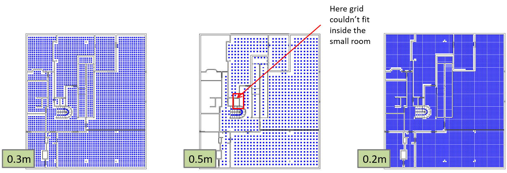
This means that before to start the analysis it is important to generate appropriate grid for a project geometry: not so dense to not make it calculate forever but also not too sparse to obtain valid results further.
7. “Create Vantage Points And Section By Rooms” Component
Nevertheless, another approach could be used to generate grid points and avoid the problem with small door spaces.
The component “CreateVantagePointsAndSectionByRooms” from the same “Grid” tab generates grid separately for each room boundary, therefore, for this component it is also possible to control the areas where grid will be generated and where will not more precisely, which could reduce the computation time at the end.
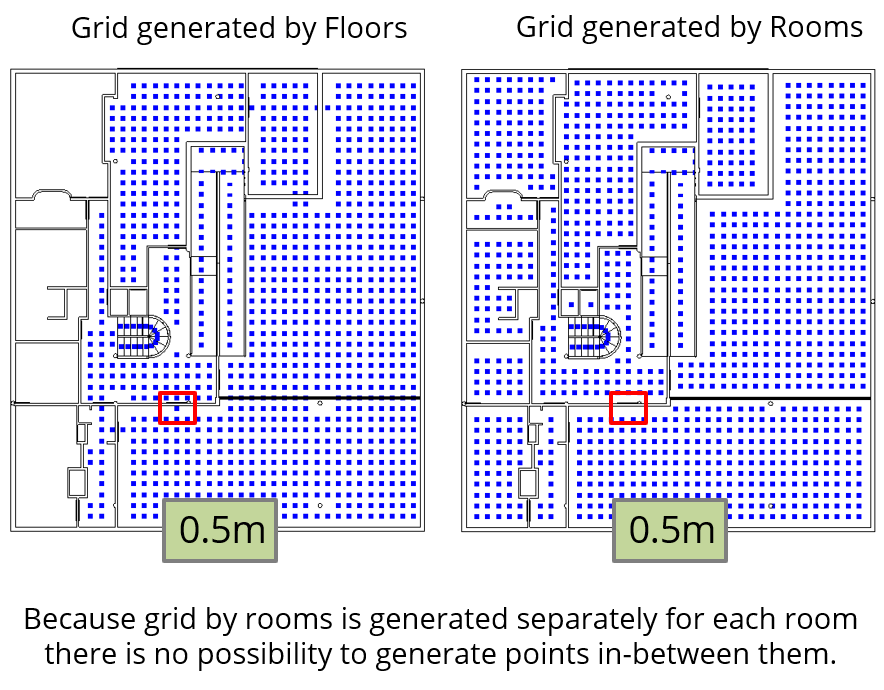
The “CreateVantagePointsAndSectionByFloors” takes into account door spaces and creates points in such areas (highlighted by red square on images), where the “CreateVantagePointsAndSectionByRooms” generates grid inside the room and couldn’t include door areas. This is important for a further accessibility analysis where it is needed to be specified which distance is allowed between two point to consider them as “connected” (will be discussed further).
SUM UP