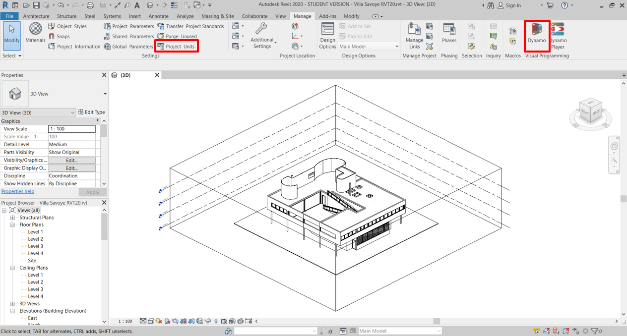
1. Open Test project
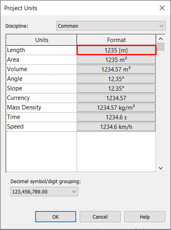
Download test Revit project (“Villa Savoye RVTXX.rvt”) and open it. Check that project units are set to meters. Then launch Dynamo.
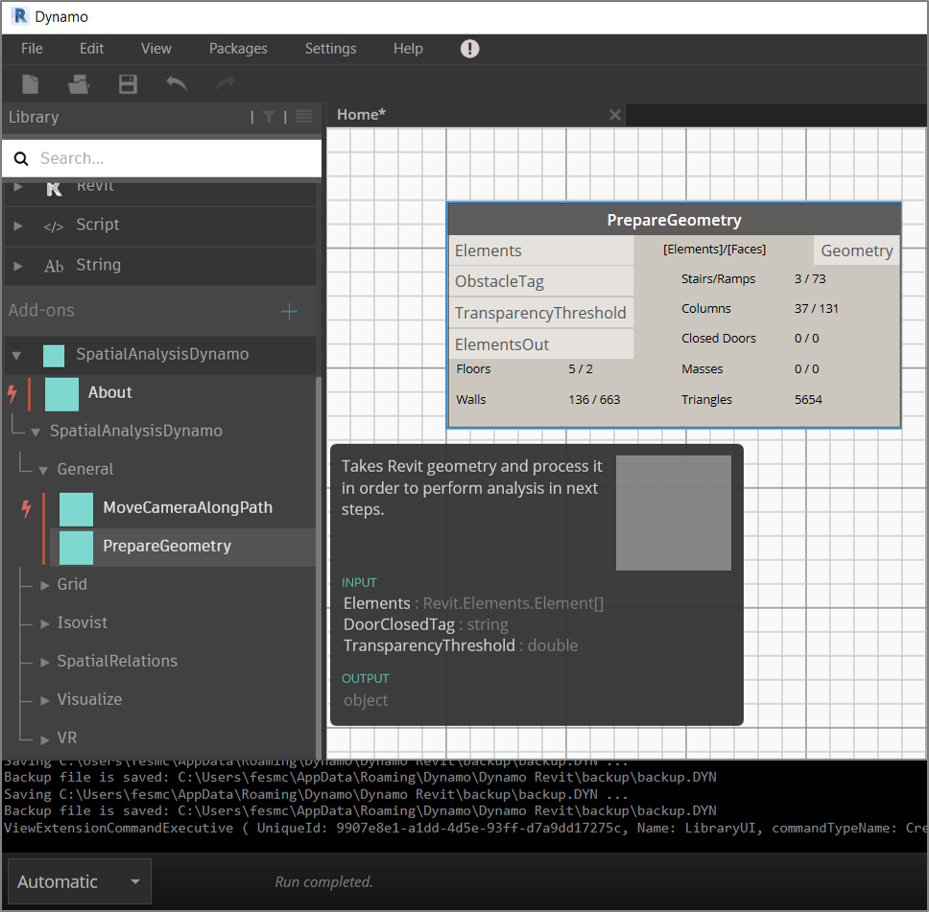
2. Add “Prepare Geometry” Component
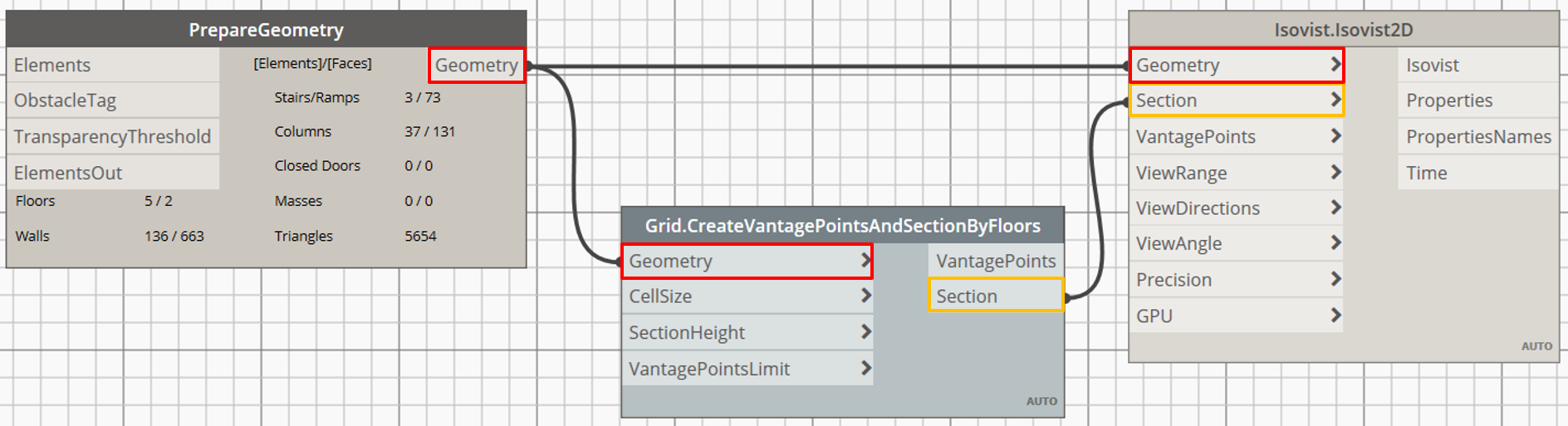
Add the “PrepareGeometry” component from the “General” tab to the canvas. This component is a start point for almost all workflows in this package. It processes all necessary Revit geometry in order to perform analysis in next steps with other components.
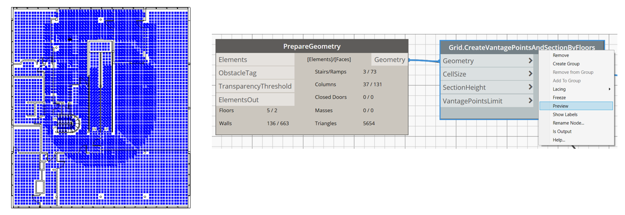
3. Add “Create Vantage Points And Section By Floors” component
Add the “CreateVantagePointsAndSectionByFloors” component from the “Grid” tab to the canvas. This component is also frequently used during various workflows. Connect the “Geometry” output from the “PrepareGeometry” component with the “Geometry” input of the “CreateVantagePointsAndSectionByFloors” component.
4. Add “Isovist 2D” Component
Add the “Isovist2D” component from the “Isovist” tab. Connect “Geometry” output of “PrepareGeometry” component with corresponding input. And also connect “Section” output of “CreateVantagePointsAndSectionByFloors” with corresponding input of “Isovist 2D” component.
5. Select vantage point
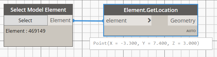
The “Isovist2D” component could build isovist for one point as well as for many (i.e. for list) vantage points. In this tutorial we will build isovist for one vantage point. As vantage point we select an object from Revit project. In the opened test project file find some standing human model (There is one human on level 1 and another is on level 2). Return to the Dynamo environment and add “Select Model Element” component to the canvas. Click “Select” button and select human object.

Now, after we’ve selected the human object, we need to extract its location (a point with 3 coordinates: x, y, z) in the project. For this purpose add the “GetLocation” component to the canvas and connect it with “Element” output of “Select Model Element” component. The “GetLocation” component will return a point, which you can check by hovering mouse on the component.
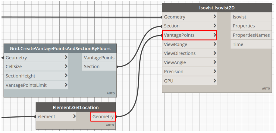
Having a vantage point, connect the “Geometry” output of the “GetLocation” component with the “VantagePoints” input of the “Isovist2D” component. Now, when all required inputs are connected, the component should be activated (component header then should become dark gray).
6. Display isovist rays
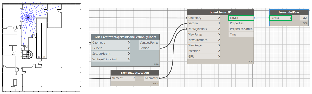
To display rays geometry add the “GetRays” component from the “Isovist” tab. Connect the “Isovist” output of the “Isovist2D” component with the “Isovist” input. After this - rays will appear in active Revit view.
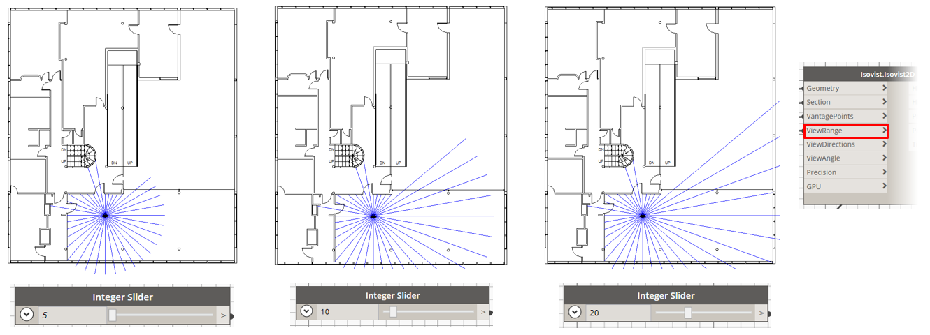
7. Isovist settings: View range
You can manipulate geometry of isovist by input parameters. First “ViewRange” input controls a length of rays outcoming from a viewer position (i.e. vantage point) and defines how far one can see. Default value is set to 20m.
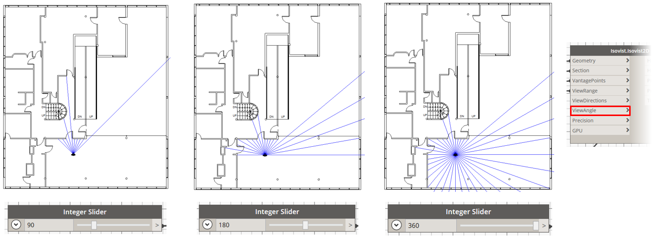
8. Isovist settings: View Angle
The “ViewAngle” input controls viewing angle and defines the field of view. Default value is set to 360°.
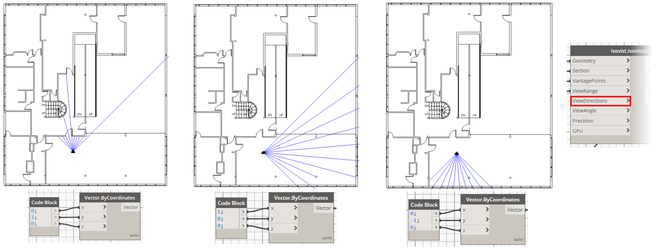
9. Isovist settings: View directions
The “ViewDirections” input controls direction vector for a vantage point and defines in which direction the viewer looks. It is not taken into account, if “ViewAngle” input is set to 360°. By default the vector is set to (x:0, y:1, z:0). In order to create a vector add “ByCoordinates” component from the “Geometry”→ “Abstract” → “Vector” tab.
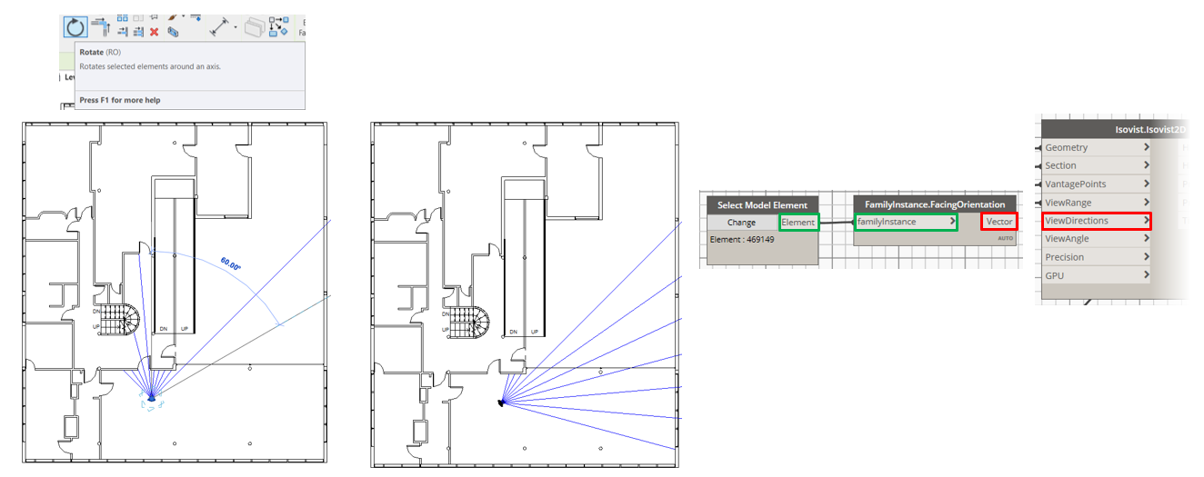
It is also possible to rotate the human object in Revit view and get rotation as direction vector input. Add component “FacingOrientation” from the “Revit” → “Elements” → “FamilyInstance” tab. Connect the “Element” output from the added earlier on step 5 “Select Model Element” component with the “FamilyInstance” input. The “FacingOrientation” component then returns a vector which can be provided as the “ViewDirection” input. After you connect them, the rotation of the human object will cause changes in the isovist rays position too.
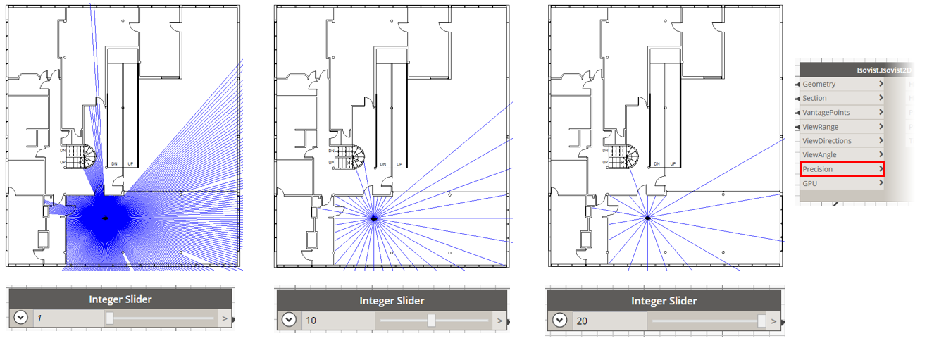
10. Isovist settings: Precision
The “Precision” input controls a step angle between generated rays. By default it is set to 10° between rays. The denser rays generation is, the more precise isovist geometry is built, but the more time could be required for calculations.
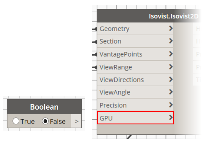
11. Calculation acceleration
Our current example is not so difficult to calculate and it takes a very little time, but in a case of large number of points, very dense rays generation (with high precision) and with a long view range – it could take a while to obtain results. Therefore, a GPU (graphics processing unit) acceleration is included into the component for CUDA supported video cards. “GPU” input waits Boolean (True/False) value and by default is set to False, which means that all calculations are done on CPU (central processing unit). Add “Boolean” component and select the radio button you need.
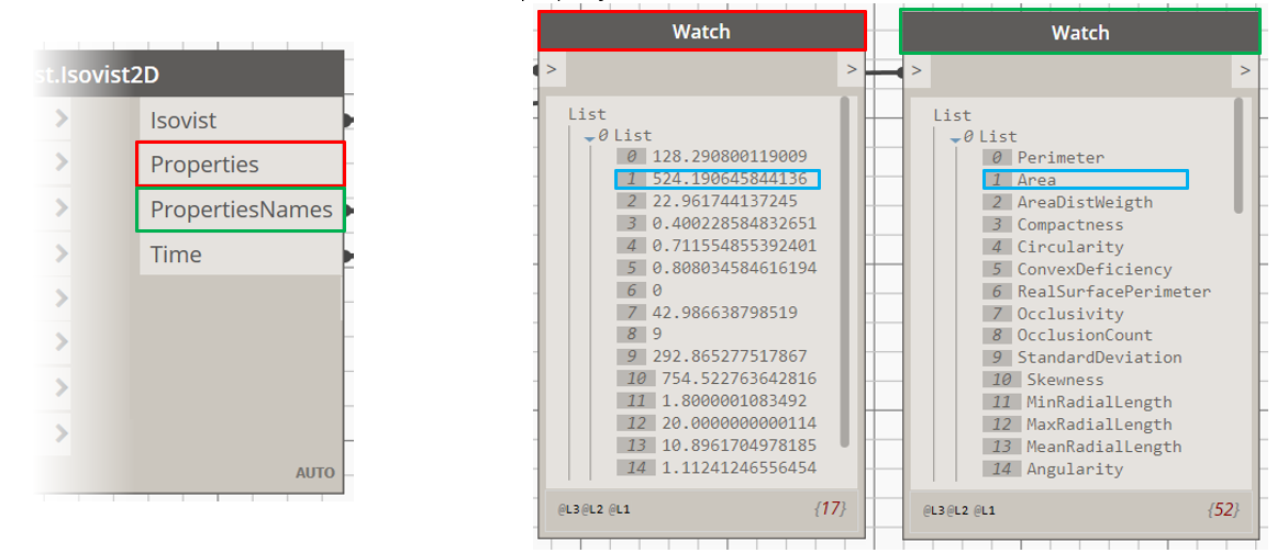
11. Isovist Properties
The “Isovist2D” component calculates not only the rays geometry but also isovist properties per each vantage point. It returns the list of properties values as “Properties” output and their titles (0 List), description (1 List) and units (2 List) as the “PropertiesNames” output in the same order. Add the “Watch” component and connect it with “Properties” output to see the values. Do the same action for the “PropertiesNames” output. Matching two lists we can say, for example, that the “Area” is equal to 524.19 m2, the “Skewness” is equal to 754.52 and so on (see lecture to know more about each property).
SUM UP